I’m sick of hitting potholes and I wish the streets were in better repair so I’ve decided to take matters into my own hands. I eventually would like to build a completely automated pothole detection and reporting system using a microcontroller, an accelerometer and a GPS. Should this become too difficult to complete, I’ll drop the project, it’s only for fun after all.

Maybe I'm giving CalTrans too much credit, but I figure that CalTrans is probably unaware of a lot of the pot-holes that exist. How exactly would they know of one short of driving over it themselves on their way to work? Which makes me wonder. Are the roads better on the paths that CalTrans employees take to work daily?
Anyhow, I'd like to help them get a hold of the pot-hole problem.
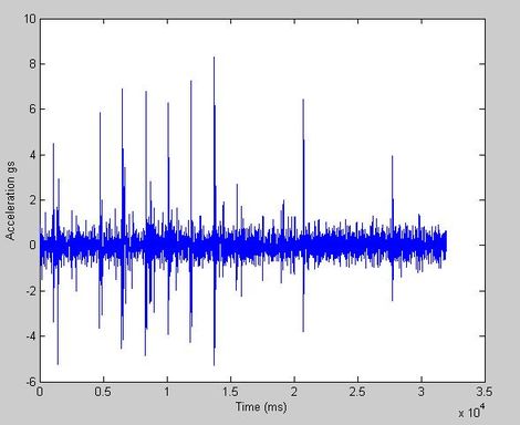
At left is the signature of the "braille" on the center of the road by my house when driven over at 40 mph. You can easily pick out the regular peaks in the plot caused by each little braille bit. I hope to get things calibrated so that I can tell the difference between "braille" and actual pot-holes. The first order approach is simply to check the direction of the acceleration. Pot-holes are holes and road "braille" is sets of bumps. Thus, the initial acceleration due to the two should differ in sign.

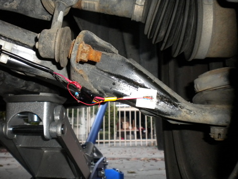
Today I tried out the basics of the pothole detection setup. I wired up an accelerometer to a DAQ that plugs into my computer. I drove around and recorded bumps that I ran over with the tire my accelerometer is connected to. Above is a quick video explanation of the setup. For those of you unfamiliar with electronics, DAQ is Data Acquisition and usually refers to a device such as the blue thing in the video above. To the right is a picture of the accelerometer glued to the front right swing-arm of my Honda Civic. The white square is the sticky-pad I used to glue it down. The leads are routed back into my car and connected to the DAQ which is in turn connected to my computer. The image at top is a plot of the “brail” reflective bumps that are spaced every 15 or so yards between lanes. You’ll notice how the spikes are regularly spaced, and that after I hit six in a row, I missed two, hit one and then missed two more. These “brail” proved pretty effective as calibration bumps.
 RSS Feed
