The wing above was constructed of depron ribs, a depron-balsa forward spar and a depron rear spar. I get my balsa from my local hobby store, and I get my depron sheets from RC foam.
Depron happens to be a great material for making lightweight aeronautical structures such as wings for gliders and airplanes. If you’ve never ordered depron and you’re wondering what it is, you’ve probably had depron in your hands before. Where you ask? Well if you buy a cut of steak or some meat at the grocery store, the tray that it comes in is very made of depron.
Although depron is pretty formable, and easy to work with, it will crease or crack more easily than EPP. It is however much lighter than EPP and much smoother making it great for wings you won’t be too rough on. I wouldn’t recommend it for a combat glider however.
To make the wing shown above I selected an appropriate airfoil for my purpose using the UIUC airfoil database. I had a couple airfoils that I’ve used in the past and I experimented with some new ones using XFOIL to generate the lift/drag polars of the airfoils. In this particular case, I was needed a symmetrical airfoil and I used the NACA 0009.
There are various programs that will plot the airfoils for you, but I find it easiest to plot them in either excel, or your favorite plotting software. From there, you can easily scale them to have the chord length that you want.
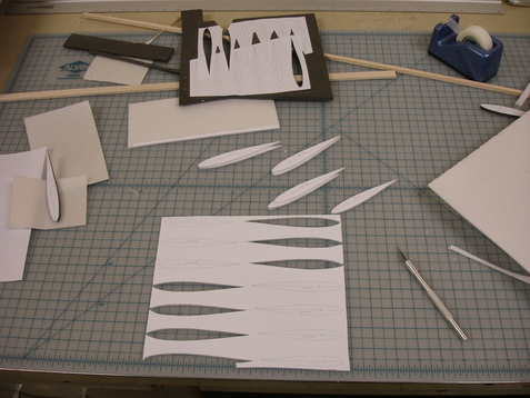
Once you’ve scaled the airfoil, I recommend trimming it by the thickness of the skin you will be using to wrap your wing unless you’re using cloth or other extremely thin material. In my case I used 1mm depron and I subtracted 1mm from the airfoil all around the ribs so that the final wrapped wing would be the airfoil I had chosen.
After scaling the airfoil and adjusting it for the skin thickness of your wing print out the airfoil and glue the printed piece of paper to something more rigid like card-stock or aluminum and trim. Then trim it to match your print. Now you’ve got a template for your airfoil and you just need to keep placing it on the depron sheet you’ll use to make your ribs and cut them out with an X-acto knife.
After scaling the airfoil and adjusting it for the skin thickness of your wing print out the airfoil and glue the printed piece of paper to something more rigid like card-stock or aluminum and trim. Then trim it to match your print. Now you’ve got a template for your airfoil and you just need to keep placing it on the depron sheet you’ll use to make your ribs and cut them out with an X-acto knife.
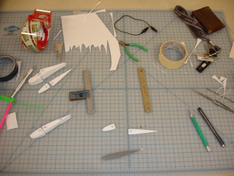
Once you’ve cut out a bunch of ribs, you’ll want to cut out a section of the rib the thickness of whatever you’ll be using for your spar about 20-30% rear of the leading edge. Now, using foam safe glue (and foam safe accelerator) glue the ribs to your spar. If you’re using a trailing edge spar, you’ll want to do a similar thing cutout toward the rear as well to leave room for your rear spar.
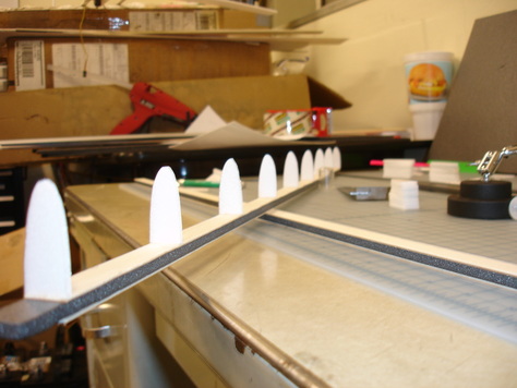
Glue everything together being careful not to introduce any unwanted twist to your wing.
Once you get the wing skeleton complete it’s time to add the skin. The depron (1mm) will easily make bends with a radius of a centimeter or so, but any smaller than that can be difficult. Notice that the depron does not resist bending equally in both directions. One direction will bend fairly easily while bends made at 90 degrees to that are difficult to make. You’ll probably want to set things up such that the easy to bend direction is parallel to your wing to make construction the easiest and give your wing the most rigidity.
When making bends of a tight radius (if you’re making a small wing) I found it best to pre-crease the region in which the tightest bends were to be made by drawing lines down the depron with a dull, HB or H pencil. This crushes the depron to some degree making the bends easier. If you’re making a pretty tight bends draw many lines close together. If you’re making less tight bends you’ll need fewer lines and these can all be spaced further apart.
Get your depron all lined up with the wing and start glueing and rolling it over your ribs. You’re only minutes away from a completed extremely lightweight wing now.
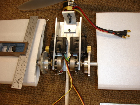
The depron wing made above was used for a mockup of what was to be a VTOL UAV platform. In the two lower pictures you see the wings connected to potentiometer shafts which were in turn connected to servos via a gear mechanism.
This setup allowed me to rotate the whole wing similarly to an aileron on a normal wing. The servos were modified so that the feedback potentiometer that “tells” the servo where in its range of motion it is was disconnected and instead the leads were connected directly to the potentiometer to which the wing was attached. This setup allowed me to introduce one more gear stage to a servo thereby increasing its effective output torque while maintaining the position control that a servo has built in. You can see a video of this setup in action by clicking this link.
The skin shown on the wingtip is made of 1mm thick depron foam.
This wing actually broke during some testing at the initial stages of a project of mine. I had not adequately reinforced the inboard section of the wing and the connection between the wing and fuselage. Remember, the bending moment goes roughly with the square of the distance from the wingtip. In my case, it went with the cube (to some approximation) because my wing was spinning about the root as does a rotor on a helicopter.
If you want to see me break my lovely wing you can check out the video below, or check out the droptest.
 RSS Feed
