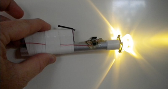
I guess it falls under the category of “if you want something done right you’ve got to do it yourself.” Well, I’ve been searching for a great LED flashlight, but I don’t want to be buying batteries all the time, and I don’t want to remove the batteries to charge them. What’s the solution? A lithium ion battery powered, USB chargeable, constant-current, LED flashlight. The above picture shows my fully functional prototype. I epoxied the LED to the front end of an aluminum rod for heat-sinking purposes, and I dead bug’d all the components. The collimator came with an adhesive back, and is designed to fit around the specific LED I used. I can now use this flashlight, and charge it with my iphone, or ipod charger, which I never go anywhere without. Any USB port will also work for charging. The only problem is the packaging, but if I get around to it I’m going to gut a cheapo harbor freight flashlight and put the guts from a second prototype inside.
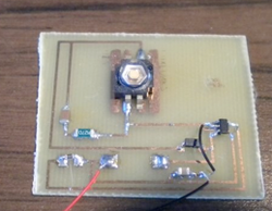
I’ve even made my first board. PCB with photoresist already spun onto it is available somewhere on the internet, but my roommate just happened to have some and the chemicals for etching it. Anyhow, I took a stab at drawing it all up in Eagle, then I printed the traces and pads onto transparency film and taped that over the PCB and exposed it under UV light. From there, it’s just like old fashion black and white photography. Dip it in this, then that, then rinse and voila, you’ve got a PCB. I’m obviously not making the best use of the space on the PCB, but it was a first attempt and it actually worked. This picture of it is after I moved, and the inductor for the buck/boost is missing.
BOM:
I recommend checking out www.maxim-ic.com (not maxim.com as I learned the hard way) before you start your project because they have free samples of various IC’s available.
I’ve even made my first board. PCB with photoresist already spun onto it is available somewhere on the internet, but my roommate just happened to have some and the chemicals for etching it. Anyhow, I took a stab at drawing it all up in Eagle, then I printed the traces and pads onto transparency film and taped that over the PCB and exposed it under UV light. From there, it’s just like old fashion black and white photography. Dip it in this, then that, then rinse and voila, you’ve got a PCB. I’m obviously not making the best use of the space on the PCB, but it was a first attempt and it actually worked. This picture of it is after I moved, and the inductor for the buck/boost is missing.
BOM:
- Luxeon LED
- Maxim Li-ion IC: MAX1555EZK+T
- National Semiconductor LED drive IC: LM3410XMF/NOPB
- Various resistors, capacitors, and inductors
- Mini-USB plug
- Li-ion batteryCollimator lens
I recommend checking out www.maxim-ic.com (not maxim.com as I learned the hard way) before you start your project because they have free samples of various IC’s available.


 RSS Feed
