The very first step in the development of the rotoplane was to build a mockup of the plane with limited functionality. I decided to determine whether an airplane with with wings that could rotate about their quarter chord could be made to auto-rotate. This was the basic concept of the rotoplane and if this didn’t work I thought I might as well find out sooner rather than later.
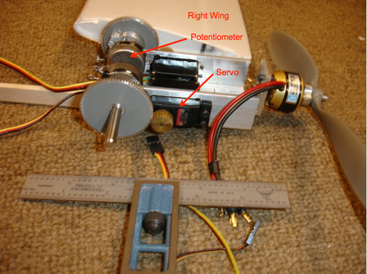
I built a set of wings out of light foam and balsa wood. Then I modified some servos so that I could attach the wings to a mockup airplane fuselage. I would have preferred to strap the wings directly to the servos, but the bearings in the servos cannot take the radial loads that would be applied in an autorotation. I needed to connect the wings to something structural yet be able to control the pitch of the wings. I opted for a solution that took advantage of how servos are designed.
Servos are essentially a geared-down brushed DC motor with a gear train. The output of the gear train is the output shaft of the servo and is connected to a potentiometer. The potentiometer is setup as a voltage divider, which feeds back into the servo control circuitry. Based on the voltage of the potentiometer, the servo position is known to the control circuitry. The control circuitry works to keep the servo at a given position for a given input.
I disconnected the internal potentiometer and re-wired the connections to an external potentiometer to which I connected the wings. Then I coupled the potentiometer and wings to the servo with an additional set of gears. In this manner I was able to de-coupled the loads on the wings from the servos allowing me to use relatively lightweight servos.
Using modified hobby electronics I was able to control the “pitch” of the wings much like the pitch of a propeller is controlled on an aircraft, or the blades of a helicopter are controlled in what is called collective. I connected a battery to the setup and an remote control receiver.
It was time to find something to drop the mockup rotoplane from to see if it could autorotate.
I live in Pasadena, known for the elegant Colorado Street Bridge. I climbed up underneath it and dropped the mockup while my brother controlled the pitch of the wings via remote control.
You will notice that in the beginning of the video the wings are facing more downward than horizontal. As the mockup dropped the rotational velocity increased and the pitch of the wings was gradually increased until they passed from being driven by the air they were falling through to pushing enough air down in order to rise up and arrest the descent of the craft.

 RSS Feed
