Chez Marc Grossman
  • Home
  • Blog
  • Tahoe Cabin

More Shopping... for CNC Brains

5/6/2016

 
I did a fair bit of reading up on LinuxCNC and watching YouTube videos before settling on what I ended up putting in my lathe for brains. I could have bought an off the shelf Fanuc controller or something like that, but let's face it -those are extremely expensive.

There is lots of talk about the hardware requirements for LinuxCNC. I was a little worried about them because it can be hard to find a computer with a parallel port these days, especially one that has any decent performance. Then, even with a computer that does have a parallel port if the computer's parallel port is generating the step and direction pulses for the servos you've got to make sure it can reliably generate evenly spaced pulses pretty quickly unless you're ok with really slow servo speeds or jerky movements.

One of my main goals was to be able to thread on my CNC lathe. As such I knew that I'd need a spindle encoder with that comes process control. When cutting a thread on a lathe, the X axis is set at some depth and then the Z is moved at some rate proportional to the spindle RPM to generate a specific thread pitch. For example, say I want to cut a 1.0" 20 TPI thread and the spindle is moving at 300 RPM. For every revolution of the spindle, the Z axis will need to move 0.050". It must do this smoothly or you won't get a nice clean thread. It must also do this many times starting with the cutting edge of the threading tip at say 0.990", then at 0.980, then maybe 0.975 and so on all the way down to maybe 0.924" for a full 100% thread. Each time it moves in in diameter and starts a new cut it must enter the cut where the groove of the thread already is, or it's cutting a new thread that is rotated with respect to the previous thread.

As you can imagine this is a complicated ballet. The brains need to know where the spindle axis is in its rotation all the while knowing where the Z axis is so that it can feed the cutter into the thread at just the right moment. This is where the process control comes in. One axis must wait for another axis and make it's movements proportionally to the movements of the other axis. 

With process control there must be feedback from the brains to the servos. Say the spindle isn't turning quite as fast as it was told to turn, the Z axis must be delayed in the case of the threading example. The real question is where does this process control happen. I wasn't sure where it happened and didn't want to dive headlong into LinuxCNC code to find out. I decided to take a chance. Instead of buying a tower computer with a parallel port I decided to get a MintBox and connect my "motion controller" via ethernet. I figured that for this way to work, the only way that was possible was that the Mesa card would be buffering commands and also handling the spindle synchronization.
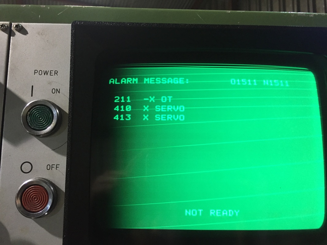
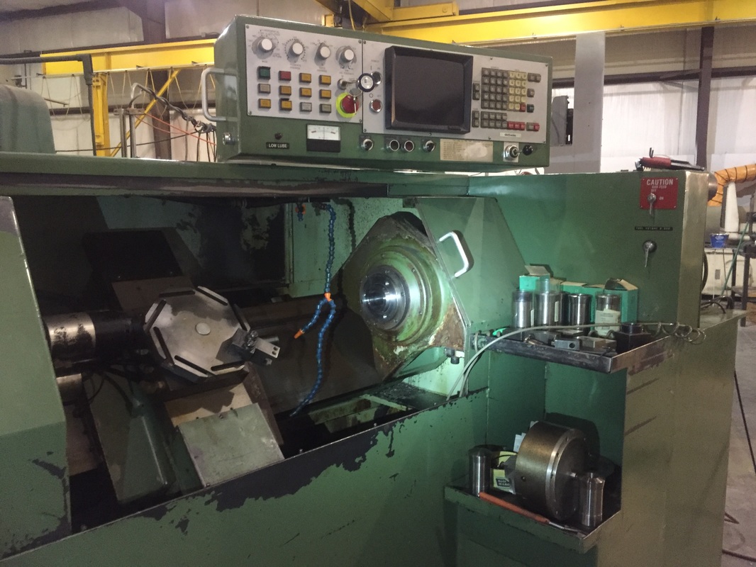
Here is a sneak preview of how things worked out
As explained previously, without fully understanding the system I opted for the Mesa cards. I'm going to jump forwards a few months here and tell you how it worked out.

I made absolutely the right decision. 
Mesa Electronics makes a fantastic bunch of electronics for amazing prices. I was able to get my lathe up and running using their product and a pretty basic computer that certainly didn't have the max-jitter requirements recommended by LinuxCNC. I can't say enough good things about the Mesa cards. There is no way anyone could make as good a setup as I have with a tower computer and a parallel port. As you'll see later in this blog when I publish my .hal and .ini files I can generate steps much faster than any parallel port and much more consistently.

I decided to use a Mesa Electronics 7i92E and 7i76 breakout board for the 7i92E. If I had been only slightly more clever I would have used the 7i76E which is basically a 7i76 breakout with a 7i92 on it and it would have saved me a few bucks. The reason to use the 7i92E and a 7i76 is that I think you could plug two 7i76's into a 7i92 in case you needed more axes or more I/O pins.

The Mesa cards are FPGA's, and as such are extremely fast at the "math" they're programmed to do. For example, if I remember correctly, the spindle encoder input on the Mesa 7i76 is good to 10 MHz. There is no way that the parallel port on any computer could read encoder inputs at 10 MHz.

LinuxCNC makes a big deal about determining if your computer is fast enough to properly run the various threads. In the standard parallel port configuration it needs to be a really fast computer so that steps are generated at the proper timing and aren't interrupted by some other process on the computer. With the Mesa cards I wasn't sure that this was the case. My reasoning here was that the step generation is done by the FPGA and I was pretty sure it was buffered since it's via eithernet and there is enough overhead with the ethernet protocols that latency would be an issue if things weren't buffered.

The FPGA runs at a clock frequency of 50 MHz, so it could theoretically generate something like 50 million steps per second if it could do one every clock cycle. I've got 20,000 count per revolution servos that can go up to 3000 RPM . At full speed of 3000 RPM I'd need 1,000,000 steps per second. That seemed to give me plenty of headroom. It should also be noted that at 3000 RPM my axes would be moving at 600 inches/minute which is much faster than I'd be comfortable with anyways.


Anyhow given all this I made a bet on the Mesa card, and it's really paid off. That said, because I went that route, most tutorials and information on the internet had to be slightly modified to meet my needs, but it really wasn't a big deal.

Going Shopping

5/1/2016

 
I now needed:
  • A spindle motor (Automation Direct)
  • X-axis servo (Dorna)
  • Y-axis servo (Dorna)
  • Servo controllers/amplifiers (Dorna)
  • Spindle motor controller (Automation Direct)
  • Spindle encoder (US Digital)
  • Brains (LinuxCNC, mintbox computer, Mesa 7i92 and 7i76)


Here is what I settled on.
  • Spindle motor from Automation Direct: 5 HP TEFC 3 phase 208/220VAC 1800 RPM with a max speed of 2700 RPM.
This seemed like a good choice to me because the original spindle motor was 7.5 hp and 3000 RPM. I'm not going to be turning really small stuff so spindle speed isn't a major concern. Also, I'm not going to be running this machine in a production shop where every second counts so I didn't see the need to have as much power as the original motor had. We'll see if this turns out to be a problem, but I doubt it. The 7.5 hp motor from Automation Direct, and the larger VFD to drive it would have cost me an extra few hundred so I settled on the 5 HP.
  • Servos:
I found someone selling AC servos with servo drivers on eBay for a very reasonable price. They were also the right size and seemed to have plenty of torque so I jumped on the opportunity. I got all three sets of servo and driver for $800. Here are a few pictures of the servos. They had the same mount as the original servos and they looked to be about the right power/torque so I took a chance. Also, how can you beat a deal for 3 1.2kW 3000 RPM servos and drivers for under $1000?
For spindle control I bought a GS2 VFD that was sized for my motor from Automation Direct. Among other speed control inputs it takes a 0-10V input which was convenient because the breakout board I'm planning on using has a 0-10V spindle speed control output.​

As you might imagine this was a welcome first step. It certainly appeared that my lathe spindle bearings were ok.

Gutting it!

4/8/2016

 
I decided to rip everything out of the machine except for the spindle, the ways, and the ball screws. I removed the 300 lb commutated coreless brushed DC motor which was the spindle, I removed both servos, I removed the tape reader, I removed the control panel, I removed the old DC servo drivers. When I got done it was quite terrifying, but it also made me feel a hell of a lot better. Rather than having a bunch of late 70's electronics that I was unable to determine whether they were in working condition I had a mechanically complete machine missing only brains and motive devices.

Check out the stuff I ripped out

Why Did I Buy the TBI Lathe

3/30/2016

 
Well, it was for sale as-is. I was told that I could move the axes around and turn the spindle on. I moved Z back and forth a few inches, and then moved X up and down a few inches before I got a bunch of alarms. I backed the X axis away from the overtravel position and hoped that would clear the alarm, but it didn't. I was unable to clear the alarm and had to buy the lathe. Fortunately, I bought it for near scrap metal price. It also came with two pneumatic collet closers and a air-chuck, as well as about 10 Hardinge 215 collets.

At that point I was pretty worried about how this project was going to play out. I had hoped to use the lathe a little bit in its original configuration before going for a LinuxCNC retrofit, but I guess that just wasn't in the cards. I read the Fanuc manual and tried everything but was unable to clear the alarm and get the machine going.
Picture

I decided to have a look at the servo that was giving me grief and this is what I found.

Picture
So here I was with 6000lbs of worthless steel and I had to make a decision as to whether or not to invest a significant amount of time and money in a retrofit or scrap the project. After a few days of deliberating I decided to start ordering parts.

Bought a Lathe

3/20/2016

 
I've been wanting a CNC lathe for some time. It might be said that I have a lathe obsession. I've already got a Hardinge Chucker which is a damn fine machine.

My chucker is a turret lathe that was built in the 70's. It could be said that it's about the last top-of-the-line non-CNC lathes ever built. Pretty quickly after the 70's CNC lathes took over and the need for chuckers went away. It's a fantastic lathe and mine happens to be in incredible condition. It has an 8 station turret and using it I'm able to make parts with amazing accuracy and great speed. My only complaints with it are that it uses 5C collets which don't have much in the way of capacity so you can't turn stock over about an inch. I do have a three jaw scroll chuck for it but I'm still limited by the spindle through hole. The next "problem" is that I never got the threading attachment for it because they're hard to come by, somewhat expensive, and you need a different threading die for every thread pitch you want to cut.

I got it in my mind that I'd add servos to it and make it CNC, but the more I looked into it the more lost interest. My Chucker is in impeccable condition and I decided that I'd hate to screw up what is an amazing piece of good old American machinery; I started looking elsewhere.

What I found was a Tomlinson Brothers Inc (TBI) lathe. It's an eight station turret lathe like my Hardinge Chucker but it uses 215 collets which can fit 1.75" stock. The through hole is about 2.0" so I can put some fairly large stuff through it. It's also CNC.

This is what it looked like when I bought it.
Picture

Pot-hole Detection and Reporting (I'm sick of pot-holes)

8/29/2011

 
I’m sick of hitting potholes and I wish the streets were in better repair so I’ve decided to take matters into my own hands. I eventually would like to build a completely automated pothole detection and reporting system using a microcontroller, an accelerometer and a GPS. Should this become too difficult to complete, I’ll drop the project, it’s only for fun after all.
Picture
Maybe I'm giving CalTrans too much credit, but I figure that CalTrans is probably unaware of a lot of the pot-holes that exist. How exactly would they know of one short of driving over it themselves on their way to work? Which makes me wonder. Are the roads better on the paths that CalTrans employees take to work daily?
Anyhow, I'd like to help them get a hold of the pot-hole problem.

At left is the signature of the "braille" on the center of the road by my house when driven over at 40 mph. You can easily pick out the regular peaks in the plot caused by each little braille bit. I hope to get things calibrated so that I can tell the difference between "braille" and actual pot-holes. The first order approach is simply to check the direction of the acceleration. Pot-holes are holes and road "braille" is sets of bumps. Thus, the initial acceleration due to the two should differ in sign.

Picture
Today I tried out the basics of the pothole detection setup. I wired up an accelerometer to a DAQ that plugs into my computer. I drove around and recorded bumps that I ran over with the tire my accelerometer is connected to. Above is a quick video explanation of the setup. For those of you unfamiliar with electronics, DAQ is Data Acquisition and usually refers to a device such as the blue thing in the video above. To the right is a picture of the accelerometer glued to the front right swing-arm of my Honda Civic. The white square is the sticky-pad I used to glue it down. The leads are routed back into my car and connected to the DAQ which is in turn connected to my computer. The image at top is a plot of the “brail” reflective bumps that are spaced every 15 or so yards between lanes. You’ll notice how the spikes are regularly spaced, and that after I hit six in a row, I missed two, hit one and then missed two more. These “brail” proved pretty effective as calibration bumps.

Grand Canyon Tour (from Los Angeles)

5/22/2011

 
It's early May and the weather is finally cooperating with my desire to go flying. I've been telling a college buddy of mine that I'd take him flying for months and just haven't gotten around to it. Yesterday however I finally made due on a promise.

Adam Goldstein and I flew out to Las Vegas. We left Whiteman airport (WHP) at about 0800 and arrived at Boulder City Airport (BVU) about 90 minutes later. That sure as hell beats the 3+ hour drive that is more typical of a trip to Vegas. Along the way, our route took us over the BrightSource Ivanpah solar power tower construction site an we snapped some photos. Then we flew over Nevada Solar One, and a PV plant located adjacent to it and snapped some more photos.
Picture
Adam Goldstein -Looking terrified and hoping is mother never finds out about this.
When complete, the BrightSource Ivanpah facility will be the largest solar thermal power facility in the world. It has a nameplate rating of 396 MW -that's as large, or larger than many conventional coal, natural gas, or oil power plants.

Solar thermal power plants are a bit un-conventional in terms of generating solar power. When most of us think solar power, we think solar panels. Solar thermal power plants however use mirrors that reflect sunlight onto a boiler where steam is made. This steam is then passed through a conventional turbine -just as the steam made by burning fossil fuels other power plants. The only difference between the two is the source of the heat. Fossil fuel power plants burn fossil fuels, nuclear power plants use heat from fission, and solar thermal power plants use sunlight.

Picture
Unit 1 of 3 at the BrightSource Ivanpah Solar Electric Generating Station.
Possibly the most amazing thing about the BrightSource Ivanpah facility is the sheer size of it. The center portion of the picture at right is where a tower will be erected. This tower will support a boiler about 400 feet off the ground. The long edges of the solar field, where the arcs are, are over a km in length. The green in the background is a golf course, and this first third of the eventual 392 MW Ivanpah facility dwarfs it.

I'm currently an employee of eSolar, technically a competitor of BrightSource's, but let's face it, a BrightSource success is a solar thermal success and good for eSolar too. Let's hope they can keep this baby on budget.

Picture
Nevada Solar One in foreground, PV facility in background.
On our way in to the Boulder City airport, we flew over Nevada Solar One -another solar thermal power plant. While still a solar-thermal power plant, the layout is different than the Ivanpah plant in that the boiler is not atop a tower. Instead, the mirrors are parabolic troughs. At the focus runs a pipe on which sunlight is concentrated. This pipe carries a heat transfer fluid that is heated and eventually used to produce steam that will pass through the steam turbine generator to make electricity. Again, the size is incredible.

Picture
Tributary of Grand Canyon.
After lunch in Boulder City, we flew out to the Grand Canyon. Navigating the airspace was a pain because of the number of helicopter flights from Vegas with tourists, but we made it and it was well worth it.

I wish we'd taken more photos, but truth be told, no photo could do it justice.

AUVSI (Denver, CO)

8/26/2010

 
Picture
Picture
High Altitude Rockies just southwest of Denver, CO.
The company I work for (eSolar) sent me to AUVSI in Denver, CO to have a look at the developers of unmanned ground vehicles. Why would they do something so awesome? Well, I designed and built the autonomous cleaning vehicles for the eSolar demo power plant in Lancaster, CA. Now we’re moving past demo and prototype and we want someone to build a better one. Our expertise at eSolar is heliostats and the software that makes our fields work. We don’t really want to be in the mirror cleaning business, but we need someone to be in that business so that they can keep our mirrors clean.


Picture
Beginnings of the Grand Canyon. The muddy little river at the bottom is the mighty Colorado.
At AUVSI, I met with various manufacturers of robotic vehicles. They all had interesting stuff, but quite frankly, the component-level hardware that was at the show was just as interesting as the vehicles themselves. I finally saw a harmonic drive in operation, I got to chat with a manufacturer of miniature turbine engines and ask him detailed questions regarding their operation, I saw a nutating engine, and I saw more AHRS’s (Altitude Heading Reference System) than you could shake a stick at.

Anyhow, the most interesting part of the trip was not the show, it was the flight out there and back. Instead of flying Southwest, I decided to fly my RV-6... that you’re pretty well acquainted with by now. On Monday August 24th after work I flew to Davis (EDU) to see my girlfriend and mom. Then early on Tuesday I took off from EDU headed for Ely, Nevada (ELY). At Ely the engine ran a little rough during my taxi to the fuel pit after landing. When I went to kill the engine by leaning the mixture it didn’t die in the usual way but kept rumbling on for a bit. Finally it quit and I got out.

Picture
Overdeveloped cumulous cloud over Barstow, CA.
I took the top cowling off to see if I couldn’t have a look at things, but the mixture adjustment is on the carb which is under the engine and having the top cowling off didn’t help me much. I reached in through the gap between the cowling and the airplane to see if I couldn’t tug on the mixture lever and see if it was loose. It wasn’t. I chatted with a buddy and decided that maybe our engine was just adjusted a bit rich and because of that I may have trouble shutting it off at high altitude.

I bought gas, did an extremely thorough run-up and took off toward Denver. The flight went quite smoothly until on landing, the engine started mis-behaving again. Again, I couldn’t quite stop the engine using only the mixture knob so I grounded the mags to kill it. It died, less gracefully than usual but it did die. I hopped out of the airplane and scurried off to the conference.

I didn’t think much more about things until it was time to fly back. Again, I performed a very through run up and the engine ran great t all throttle settings except idle. I decided that idle was the least important of the power settings and took off. I flew from Denver (APA) to Four Corners (FMN) and then from FMN to Whiteman, CA (APA).

Picture
Rain storms on the north slopes of the San Gabriels as viewed from above Palmdale, CA.
Shortly after leaving FMN I flew over the Grand Canyon by veering slightly off course to the north. The Grand Canyon is truly spectacular and I only wish that the pictures could do it justice. Unfortunately I have a bubble canopy and no picture through it is much good.

As I was flying over the Grand Canyon, I began trying to use the autopilot system that we had built for the RV. As you know it runs on an EEE-PC running some Matlab code we wrote. Unfortunately, every time I engaged the altitude hold, the autopilot would try to point the plane straight at the ground. Needless to say there we some bugs in the code. I started sifting through the bugs with the stick between my knees and in about 10 minutes I had the code working properly.

Between the Grand Canyon and Bullhead City, I was able to do some gain tuning, and with quite a bit of derivative gain, some proportional, and nearly zero integral I was able to stabilize the autopilot to some degree. It wasn’t perfect but it wasn’t so bad for a first step. All that was really missing was a low pass filter on the barometric pressure input. For some reason, spikes would appear on the barometric pressure input and these would cause the derivative error signal to spike. Needless to say this made the flight somewhat rough so I quickly coded up a running average filter and it smoothed things out quite a bit.

As I was passing the Grand Canyon and coding, I could already see cumulous clouds building on my route toward LA. I contacted ATC to see if they could inform me on where the weather was. Fortunately, the cumulous clouds were all on the San Gabriel’s just south of my route. I continued toward LA until the clouds were just off my left wing tip. Finally, as I was just south of Palmdale I noticed giant columns of precipitation and lightning. It was quite stunning. I kept trying to capture pictures of the lightning, but without a light activated shutter, or really long exposures, it’s nearly impossible to capture lightning.

Rough Engine Landing

8/26/2010

 
When I had finally cleared the thunderheads and storms mentioned in my previous blog post I headed over the San Gabriels and down into the Burbank/Whiteman area. I was fearing some sort of engine trouble because earlier in the flight my engine had been acting up at low throttle settings. I was not sure why it was doing so, but I feared it might do it again -so I hedged with altitude. I must have been 10,000 feet above my intended landing spot when I was only 15 miles out and cruising at 200 mph.

I came in over the San Gabriels pretty high and in such a way that no matter what the engine did I was sure I could make the runway at Whiteman. Sure enough, as I reduced the throttle toward idle, the engine got very rough and began to cough.

By this point I was lined up on a two mile final with about 3000’ to lose so I wasn’t sweating it. In fact I was mostly concerned with getting down in time. I continued an aggressive slip and worked the throttle to keep the engine running. Then again, as I reduced the power to idle, the engine coughed and died.

This put me in a funny position because I knew the engine was running too rich, but I hated to pull back the mixture knob to the point where it could kill the engine from being too lean. That said, I was not going to get down if the engine kept running and I didn’t want to have to go around. I decided that I was clearly going to make the airport and that once I was on the ground who cared if I had in fact landed without an engine.

I had been cleared for a straight in to runway 12 at Whiteman, but I heard the tower chatting with another aircraft in the pattern and it seemed to me that he might try to sneak them in front of me. While normally this wouldn’t be a problem, I didn’t want anyone in front of me. I’ve seen the tower call a go-around too many times because someone doesn’t properly clear the runway and I wasn’t going to get forced into a go-around situation with a rough engine. I told the tower that I was having engine trouble and that I would appreciate it if he would clear me straight in.

The tower obliged, and from that moment on I just focused on getting the plane down on the ground. The engine died a couple more times but I was always able to nurse it back to life by moving the throttle to full. In this manner I coaxed it along every 10 or so seconds with a throttle pump. I cleared the threshold and landed right on centerline. As I was making sure not to screw up at the last possible moment, the engine died again and I had to pump the throttle quickly before the prop stopped.

Anyhow, I taxi’d back to my spot got out and went in to work. I told Cedric that we had serious engine trouble and that we really needed to have it looked at. Well, a local A&P heard about the trouble and our symptoms and decided to come have a look. He reached in through the air intake and shook the carburetor saying: “well there’s your problem.”

Picture
N61764 Carburator as viewed from starboard side of aircraft. Click on photo to view web-album with pictures of the carb falling off.

It turns out that our carburetor had shook itself off the engine. We tightened the screws and all was well again. In fact he just texted me to say that he had safely landed in Napa where he is spending the weekend.

RV-6 Autopilot 4

8/14/2010

 
It’s been very interesting for me to watch the progression of the autopilot for RV-6 project. First we were just going to make an electronic trim system, then we started adding features so that we could use the electronic trim for control of the airplane for an autopilot, and now we’re writing code for control loops for the RV. I’m very much under the impression that scope creep is unstoppable and we’ll probably always be working on the RV-6 autopilot or some idea that sprouted from it.

Since I last posted to the blog, we've made quite some progress:
  • We have interfaced the Atmel to a USB-1408FS Measurement Computing DAQ
  • We have interfaced the DAQ to a computer running Matlab (without the data acquisition toolbox)
  • We have installed an electronic barometric pressure sensor in the RV-6 so that we can  measure altitude with the microcontroller.
  • We have written Matlab code to run a control loop aimed at keeping the barometric pressure constant (ie altitude hold.)
With all that work completed it was time to see if it all fits together. This we did with some beer, the Atmel STK-500, a 10 turn potentiometer, the measurement computing DAQ, an eeePC, a servo and Matlab. Here is the layout:

Picture
We connected the servo to the Atmel. To the horn of the servo, we glued a piece of balsa wood to act as a wing. We connected an analog input to the DAQ to the wiper of the potentiometer (which is simulating the output of our analog barometric pressure sensor). The servo was in turn glued to the potentiometer knob such that the wing was perpendicular to the rotational axis of the potentiometer. Then we placed the wing in wind and varied the servo to try to keep it at the same spot, which we read in based on the potential of the wiper of the potentiometer. As the angle of attack of the wing was increased it raised the wing, rotating the potentiometer and causing the Matlab program to think that our altitude had increased. Matlab then commanded the servo to a different output by sending an analog signal through the measurement computing DAQ’s analog output to an analog input on the Atmel which we convert to a pulse width for servo control.

Long story short it’s awesome. Check the video below.
<<Previous

    Author

    I've just got a lot of interests to put it simply. This is a portal into my thoughts, ramblings, and projects.

    Archives

    May 2016
    April 2016
    March 2016
    August 2011
    May 2011
    August 2010
    July 2010
    June 2010
    September 2009
    June 2008
    February 2008
    January 2008
    November 2007
    October 2007
    September 2007

    Categories

    All

    RSS Feed

Powered by Create your own unique website with customizable templates.