Chez Marc Grossman
  • Home
  • Blog
  • Tahoe Cabin

Post Title.

8/5/2010

 
I've now added some feedback for the pilot on the trim position. We decided to incorporate the addition of this bar graph so that the trim could be set to "take-off" or other known positions. This will allow the pilot to have consistent force-feedback during take-off which is a critical portion of the flight envelope.

This is all on the dev-board still, but it is working as planned and things are moving along quickly.
RV-6 Autopilot 2

7/29/2010

 
Now I’ve incorporated a second servo into the code and I’m able to control two servos independently with the ATmega32. This is all on a dev-board however and not very useful yet.

For those of you that have hobbied in electronics you know that getting something to work on a dev board is only half the battle. There is a lot that can go wrong between the dev board and a hobby box.

Here again are the steps necessary to get to where I have an autopilot in the RV.
  • Control servo with microcontroller
  • Control multiple servos with microcontroller
  • Incorporate buttons and control servos with microcontroller and package it all
  • Incorporate servo into elevator to control the trim tab
  • Put entire mechanism into RV-6
  • Verify that the trim tab has sufficient control authority (test flights)
  • Add servo control to ailerons
  • Verify that aileron servo has sufficient control authority (test flights)
  • Add sensor package to airplane that interface through microcontroller
  • Interface microcontroller with Matlab/Simulink
  • Develop control algorithms
  • Verify stability of control algorithms
  • Gain tuning
  • Port control algorithm from Matlab/Simulink to C

RV-6 Autopilot

7/24/2010

 
In the videos below you’ll see that we’ve incorporated our servo into the elevator of the airplane and we’re able to control it using the microcontroller.
In the first video we’ve incorporated the servo into the body of the elevator and it is controlling the trim tab. The microcontroller is still attached to the STK-500 dev board though and it's clearly not a well packaged setup at this point.


In this second video, we’ve removed the microcontroller from the STK-500 and placed it inside a project box that we’ll Velcro inside the airplane.

We did have some questions about how long the leads to the servo can be before there is too much noise coupled into the signal line from the power lines running next to it, but we’ve now tested things by placing about 4 meters of servo wire and had no problem. Should we develop much of a problem we can put some de-coupling capacitors on the servo, and we could always run an I2C or SPI bus to another chip at the rear of the airplane closer to the servo form which the PWM could be generated. Another option would be to use a coax, or other shielded cable for only the signal line instead of lumping it in with the power and ground for the servo. We haven’t seen any problems yet, but there is more testing to be done still.

RV-6 Maintenance Part Deux

7/23/2010

 
We’ve now put 100+ hours on the RV and it was time for a little more maintenance. We’ve been making notes of things that needed a little attention and we’re now looking into those. For example, our DG (Directional Gyroscope) used to hold its heading fairly reliably, but recently it’s been loosing its heading at a rate that surprised us. We’ve therefore taken it out to have it worked on. Of course, before we have a professional fix it, I had to play with it myself. Below, you’ll find three videos of me playing with the gyro.

In the second video what you’ll notice is that as I apply a constant force to the base of the gyroscope it rotates counteracting that force of mine and does not move. Then as the axis of the gyro becomes coaxial with the axis I’m applying the torque about the gyro freely rotates. This gyro has limits on it to prevent itself from reaching, or passing that singularity because it becomes useless at those attitudes. Furthermore, it re-centers itself such that its rotational axis is in the “horizontal” plane when you push the knob in to either adjust the heading, or simply to re-center it. This is an important note because all gyros drift and if it did not re-center itself every time you adjusted it it could easily wind up with its axis of rotation about your yaw axis of rotation (ie the world’s N,S,E,W reference frame) at which point it would prove useless. Keep in mind that the base that I’m applying torques to is connected to the heading plate in the gyroscope that rotates and indicates the heading to the pilot. With that in mind the videos should make a lot more sense.

Hood River, Oregon

7/4/2010

 
Picture
This blog was supposed to be more about the projects I’ve been working on, but I’ve decided to share some other adventures of mine with you all as well.

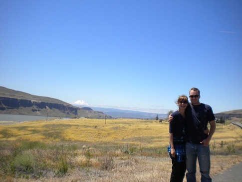
The weekend of the 4th of July my girlfriend and I traveled up to Portland, Oregon on our free Southwest flights. Since we’re in a semi-long distance relationship you would be amazed at how quickly free flights are accumulated. Anyhow, we had these free flights and we needed to use them so we thought we’d check out Hood River.

We flew in and had dinner with my aunt, uncle and cousin in Portland before driving to Hood River to camp for the weekend. During our stay, we went boating/fishing on Lost Lake, we visited the WAAAM, we went wine tasting on the gorge, we caught a sturgeon on the gorge and we took in all the beautiful scenery. That area is particularly beautiful and I hope to make it up there some day for more than just a couple days.

You can check out the pictures of our trip here: Hood River

Picture
We rented some row boats and went fishing on a beautiful lake up by Mt. Hood.

Picture
We caught some trout and ate them for dinner.

Picture
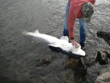
Caroline reeled in a good size sturgeon.

Picture
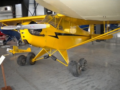
We checked out the WAAM. (Wester Area Aviation Museum). This here is an old Cub fitted with extra wheels for soft field (very soft field) landings.

RV-6 Maintenance

7/2/2010

 
Picture
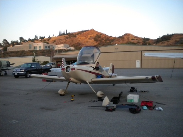
Well, I’ve taken a little break on the microcontroller stuff for the RV-6 autopilot because the plane needed a little love. It’s been flown 50+ hours since Cedric and I bought it in February, 2010 and there was some maintenance that needed to be done before a trip to Tennessee.

We took the cowling off, changed the oil, re-wired some of the electronic ignition, re-sealed the right fuel tank, cleaned up some of the wiring, replaced the fuel filters, re-plumbed some of the vacuum lines, and a couple other things. We worked every evening from about 17:30 until about 23:00.

In the end we were able to complete all the necessary work in three evenings of work and the plane was ready to go by the 3rd of July.

RV-6 Autopilot 1

6/29/2010

 
The goal of this project is to add an autopilot to my RV-6. There are many smaller steps to be completed along the way so I’ll lay out the end goals, then I’ll break things down a bit and then we’ll start from the top.

The RV-6 is a great airplane. Mine will typically cruise at about 180-190 mph on 7.5 gallons of fuel per hour. Do the math, that’s about 25 mpg! I don’t believe that there are any cars that can get you somewhere at 180 mph while only consuming 25 mpg. It’s the Honda Civic of airplanes except that it runs on 100LL.

Anyhow, the RV-6 is a two person side-by-side experimental airplane that comes as a kit sold by Van’s Aircraft. It is one of the most popular kit airplanes ever produced -a tribute to it’s incredible performance. It is rated for all kinds of aerobatic maneuvers and it’s high speed makes it a great cross country airplane as well.

Unfortunately, some of the aspects of the airplane that make it a great aerobatic airplane become drawbacks when flying cross country. Typically maneuverability is achieved with low stability, however stability would be really nice when flying cross country. It’d be great to have a plane that just tracked a course with little no pilot input. Well, that’s where the autopilot comes into play. We will use a feedback look to take what is an unstable system (or at least not very stable system) and make it stable.

Here are the steps necessary to get to where I have an autopilot in the RV.
  1. Control servo with microcontroller
  2. Control multiple servos with microcontroller
  3. Incorporate buttons and control servos with microcontroller and package it all
  4. Incorporate servo into elevator to control the trim tab
  5. Put entire mechanism into RV-6
  6. Verify that the trim tab has sufficient control authority (test flights)
  7. Add servo control to ailerons
  8. Verify that aileron servo has sufficient control authority (test flights)
  9. Add sensor package to airplane that interface through microcontroller
  10. Interface microcontroller with Matlab/Simulink
  11. Develop control algorithms
  12. Verify stability of control algorithms
  13. Gain tuning
  14. Port control algorithm from Matlab/Simulink to C

USB Rechargeable LED Flashlight

9/1/2009

 
Picture
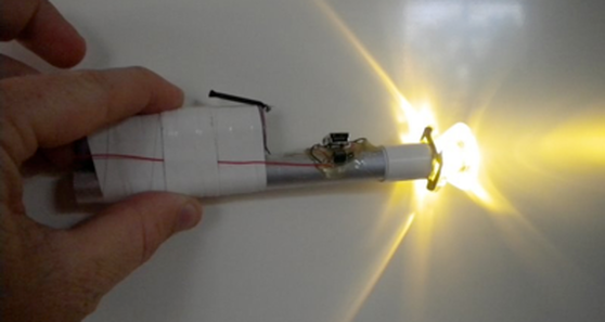
I guess it falls under the category of “if you want something done right you’ve got to do it yourself.” Well, I’ve been searching for a great LED flashlight, but I don’t want to be buying batteries all the time, and I don’t want to remove the batteries to charge them. What’s the solution? A lithium ion battery powered, USB chargeable, constant-current, LED flashlight. The above picture shows my fully functional prototype. I epoxied the LED to the front end of an aluminum rod for heat-sinking purposes, and I dead bug’d all the components. The collimator came with an adhesive back, and is designed to fit around the specific LED I used. I can now use this flashlight, and charge it with my iphone, or ipod charger, which I never go anywhere without. Any USB port will also work for charging. The only problem is the packaging, but if I get around to it I’m going to gut a cheapo harbor freight flashlight and put the guts from a second prototype inside.

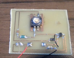
I’ve even made my first board. PCB with photoresist already spun onto it is available somewhere on the internet, but my roommate just happened to have some and the chemicals for etching it. Anyhow, I took a stab at drawing it all up in Eagle, then I printed the traces and pads onto transparency film and taped that over the PCB and exposed it under UV light. From there, it’s just like old fashion black and white photography. Dip it in this, then that, then rinse and voila, you’ve got a PCB. I’m obviously not making the best use of the space on the PCB, but it was a first attempt and it actually worked. This picture of it is after I moved, and the inductor for the buck/boost is missing. 


BOM:

  • Luxeon LED
  • Maxim Li-ion IC: MAX1555EZK+T
  • National Semiconductor LED drive IC: LM3410XMF/NOPB
  • Various resistors, capacitors, and inductors
  • Mini-USB plug
  • Li-ion batteryCollimator lens

I recommend checking out www.maxim-ic.com (not maxim.com as I learned the hard way) before you start your project because they have free samples of various IC’s available.
Picture

Rotoplane - Senior Thesis

6/6/2008

 
I've completed my thesis. You can find it below and download it.
grossman_thesis060608.pdf
File Size: 10609 kb
File Type: pdf
Download File

Rotoplane [Flight Test 3]

2/18/2008

 
We conducted another flight test over the weekend and it did not go well, but we did learn a lot from it.

The airplane was stable when under power, as it had been in previous flights. It even flew relatively well in a very stalled scenario. (It is not necessarily visible from the video, but it was very stalled throughout even the beginning of the flight.) Our problems resulted from pilot error/misinterpretation as well as from a poor configuration of the airplane prior to the flight.

Prior to take off we noticed that the rear wing of the airplane was slightly pitched down with respect to the fuselage and that the canard was slightly pitched up when the joystick was neutral. We decided that it was not extremely important for both canard and main wing to be parallel with the fuselage for flight, which we still believe is true, (I will discuss this separately) but we did not comprehend the full impact and consequences of this configuration until too late.

We had not realized that this configuration would mean that "normal" fuselage attitude during climb would actually put the canard and main wing at high angles of attack. As a result of this we took off in a stall and maintained a stall throughout without comprehending what had happened and why the airplane wasn't performing as it had in our previous flights. With the fuselage in an appropriate climb attitude it was not immediately apparent what the problem was.

Flight Analysis
The airplane took off well from a hand launch in zero wind conditions. It began to climb, but as it climbed it became apparent that it was mushing through the air rather than establishing a proper climb. The pilot then controlled down slightly, but it was not enough and the airplane continued to mush through the air. As the airplane came to a complete stall it slid right and entered a sort of flat spin. It recovered from this and began to gather speed ending the stall, but at this point we decided to autorotate in an effort to gather what we could from a failing test.


Unfortunately, prior to the flight we had decided on an autorotation sequence that was improper and could never have worked given our greater understanding of the problem at hand. This sequence was: 
  1. Kill engine
  2. Change remote control to high rate setting (this allows the pilot to rotate the wings over large angles for autorotation rather than the low angle limits used during conventional flight).
  3. Begin wing rotation (~80 degrees)
  4. Approach ground and increase angle to ~100 degrees so as to generate sufficient lift to arrest descent.

The problem with this scenario is that as soon as we killed the power we lost yaw stability and the airplane went into a bit of a flat spin. As you may recall the airplane has no vertical stabilizer. It is therefore very unstable in yaw, and cannot be maintained in coordinated, controlled flight without thrust vectoring. The ability to use thrust vectoring is lost if the motor is turned off. Thus our flight plan was doomed to fail because we had planned to cut power before entering the autorotation. The airplane was already out of control before the autorotation sequence was initiated control was never regained.

The damage to the aircraft was not as serious as it may look on video. The part of the fuselage made of aluminum bent and I will need to machine a new one. Other than that, the airplane is in good condition for future flight tests and we will be conducting these as soon as possible.

<<Previous
Forward>>

    Author

    I've just got a lot of interests to put it simply. This is a portal into my thoughts, ramblings, and projects.

    Archives

    May 2016
    April 2016
    March 2016
    August 2011
    May 2011
    August 2010
    July 2010
    June 2010
    September 2009
    June 2008
    February 2008
    January 2008
    November 2007
    October 2007
    September 2007

    Categories

    All

    RSS Feed

Powered by Create your own unique website with customizable templates.