Chez Marc Grossman
  • Home
  • Blog
  • Tahoe Cabin

Rotoplane [Flight Test 2]

2/3/2008

 
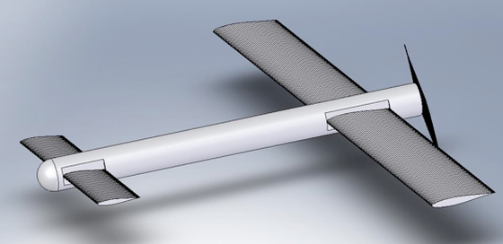
We conducted one flight test today and the results are pleasing and will certainly lead to more testing of the current airframe. The most incredible part of the flight test was that the airplane actually flew in coordinate, controlled, straight, and climbing flight. Due to various design constraints, the airplane has no vertical stabilizer and it is therefore unstable about the yaw axis. A gyroscope, and gyroscope-controlled thrust vectoring were incorporated into the design making coordinated flight possible. That said, it would be impossible for a human to control the airplane without the gyroscope. Additionally it is interesting to note, although not entirely surprising that the airplane was controllable in roll. As previously explained, there are no ailerons on the airplane. Instead, the whole main wings rotate in opposite directions to achieve roll control. I know of no other airplane that controls roll in this manner and we were all pleased to see the airplane fly as well as it did.

The rotoplane was hand launched into the wind from a moving vehicle. It climbed in coordinated, controlled flight to an altitude high enough for an autorotation. At this point the motor was cut and the airplane was set into a roll. This roll merged into a situation where the airplane was spinning about its longitudinal axis, and parallel to the gravity vector as designed.

The pilot then changed the pitch of the wings to a “positive” angle of attack. It is unclear why, but the airplane then reversed its autorotation such that the what was supposed to be the top part was now the bottom. It continued in this nose upward attitude for a brief period without rotating significantly until the controls were adjusted to accomodate an autorotation in this orientation. At this time the airplane began to rotate about an axis through the center of its fuselage although pointed upward.

Without enough altitude left to rectify the situation, the test pilot let the airplane spin up and prepared for the flare at the end of the autorotations. At an altitude of about ten feet he flared. By this point, the airplane was below the tree-line and isn’t as clearly visible as I would have liked. However, it did arrest its descent as is noted by the brief pause only a couple feet off the ground.

This test was a great success for the rotoplane even though it wasn’t a perfect demonstration of the technology being developed. It did demonstrated that an airplane of the rotoplane’s configuration could fly, and that not only could it fly; it can autorotate. Future tests will be conducted with the same airframe in a couple weeks once I have time again. 

Future work includes gathering data from the autorotation such as rotational rates, wing angle and descent rate. In order to accomplish this I would like to install electronic sensors. I am in the process of learning to program microcontrollers. I eventually hope to install some custom made data loggers in the airplane to gather data during autorotations.
I would like to thank William Grossman (UC Berkeley) who flew the airplane for all test flights from the very beginning of the project. I would also like to thank Cedric Jeanty (Caltech) for all the useful ideas and advice during the design and construction of the airplane. I would also like to thank professor Culick for his help and guidance along the way and Caltech for having a senior thesis program. Finally I would like to thank my cousin Beth for filming.
Rotoplane [Flight Test 1]

2/2/2008

 
On February 2nd, 2008 we did high speed taxi and preliminary flight tests for the rotoplane. The results are positive, but the airplane design leaves some to be desired. The most important result of the test is that the airplane has enough yaw stability to maintain straight and level flight due to the gyroscope-controlled thrust vectoring. Many high speed taxis without take offs were conducted and then we graduated to low altitude flights (1-3 feet above ground). 

All flights unfolded in approximately the same manner. The takeoff runs were smooth and transition into flight was easily accomplished with pitch control from the canard. We were able to maintain level pitch attitude and the wings parallel to the runway as well as maintain heading. The problems were always with the landings. The airplane can maintain heading when it’s motor is powered because it can vector its thrust. Upon reducing the thrust to land, the ability to maintain heading is lost and one wing slips ahead of the other. During this slip one wing generates more lift  than the other sending the plane into an awkward sort of cartwheel/roll landing as you’ll see in the videos. Fortunately, the airplane isn’t designed to land in a conventional manner.

Because the landing gear was an afterthought, designed solely for high speed taxis and initial testing, it interferes with large rotations of the main wings and thus we cannot attempt an autorotation landing from a ground roll take off. We would have liked to fly again and take off without landing gear so that we can attempt an autorotation, but it began to rain and we will have to wait for better weather.

I believe, based on my experience with the mockup as can be see in the droptest video, that we could accomplish an autorotation. Although the current airplane is heavier than that used in the droptest, the wings are much stronger and hopefully will not break as one did in the droptest. In fact, autorotation simulations in Matlab and wing loading tests confirm that the wings are strong enough and we look forward to a chance to autorotate.

See video below.

Rotoplane-3 [Mid-Year Progress Report]

1/25/2008

 
The Rotoplane is assembled and ready for a test flight. Below you'll find an in-shop demonstration of the aerial platform.

Rotoplane Drop Test

11/21/2007

 
The very first step in the development of the rotoplane was to build a mockup of the plane with limited functionality. I decided to determine whether an airplane with with wings that could rotate about their quarter chord could be made to auto-rotate. This was the basic concept of the rotoplane and if this didn’t work I thought I might as well find out sooner rather than later.

I built a set of wings out of light foam and balsa wood. Then I modified some servos so that I could attach the wings to a mockup airplane fuselage. I would have preferred to strap the wings directly to the servos, but the bearings in the servos cannot take the radial loads that would be applied in an autorotation. I needed to connect the wings to something structural yet be able to control the pitch of the wings. I opted for a solution that took advantage of how servos are designed.

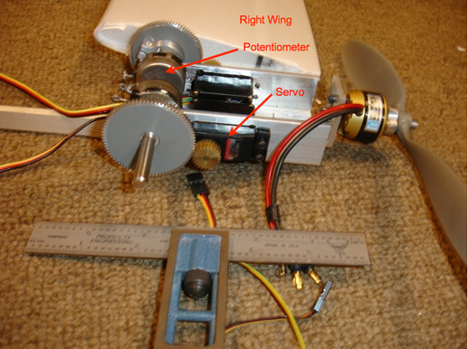
Servos are essentially a geared-down brushed DC motor with a gear train. The output of the gear train is the output shaft of the servo and is connected to a potentiometer. The potentiometer is setup as a voltage divider, which feeds back into the servo control circuitry. Based on the voltage of the potentiometer, the servo position is known to the control circuitry. The control circuitry works to keep the servo at a given position for a given input.

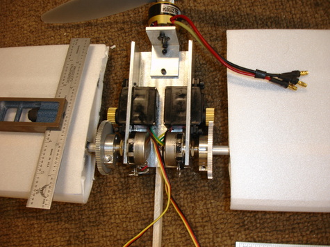
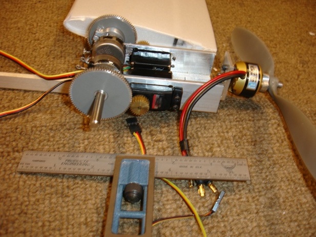
I disconnected the internal potentiometer and re-wired the connections to an external potentiometer to which I connected the wings. Then I coupled the potentiometer and wings to the servo with an additional set of gears. In this manner I was able to de-coupled the loads on the wings from the servos allowing me to use relatively lightweight servos.
Picture
Using modified hobby electronics I was able to control the “pitch” of the wings much like the pitch of a propeller is controlled on an aircraft, or the blades of a helicopter are controlled in what is called collective. I connected a battery to the setup and an remote control receiver.

It was time to find something to drop the mockup rotoplane from to see if it could autorotate.

I live in Pasadena, known for the elegant Colorado Street Bridge. I climbed up underneath it and dropped the mockup while my brother controlled the pitch of the wings via remote control.

You will notice that in the beginning of the video the wings are facing more downward than horizontal. As the mockup dropped the rotational velocity increased and the pitch of the wings was gradually increased until they passed from being driven by the air they were falling through to pushing enough air down in order to rise up and arrest the descent of the craft.

Rotoplane-2 [Droptest]

10/26/2007

 
The very first step in the development of the rotoplane was to build a mockup of the plane with limited functionality. I decided to determine whether an airplane with with wings that could rotate about their quarter chord could be made to auto-rotate. This was the basic concept of the rotoplane and if this didn’t work I thought I might as well find out sooner rather than later.

I built a set of wings out of light foam and balsa wood. Then I modified some servos so that I could attach the wings to a mockup airplane fuselage. I would have preferred to strap the wings directly to the servos, but the bearings in the servos cannot take the radial loads that would be applied in an autorotation. I needed to connect the wings to something structural yet be able to control the pitch of the wings. I opted for a solution that took advantage of how servos are designed.

Servos are essentially a geared-down brushed DC motor with a gear train. The output of the gear train is the output shaft of the servo and is connected to a potentiometer. The potentiometer is setup as a voltage divider, which feeds back into the servo control circuitry. Based on the voltage of the potentiometer, the servo position is known to the control circuitry. The control circuitry works to keep the servo at a given position for a given input.

I disconnected the internal potentiometer and re-wired the connections to an external potentiometer to which I connected the wings. Then I coupled the potentiometer and wings to the servo with an additional set of gears. In this manner I was able to de-coupled the loads on the wings from the servos allowing me to use relatively lightweight servos.
Picture
Using modified hobby electronics I was able to control the “pitch” of the wings much like the pitch of a propeller is controlled on an aircraft, or the blades of a helicopter are controlled in what is called collective. I connected a battery to the setup and an remote control receiver.

It was time to find something to drop the mockup rotoplane from to see if it could autorotate.

I live in Pasadena, known for the elegant Colorado Street Bridge. I climbed up underneath it and dropped the mockup while my brother controlled the pitch of the wings via remote control.

You will notice that in the beginning of the video the wings are facing more downward than horizontal. As the mockup dropped the rotational velocity increased and the pitch of the wings was gradually increased until they passed from being driven by the air they were falling through to pushing enough air down in order to rise up and arrest the descent of the craft.

Rotoplane Mockup

10/25/2007

 
Picture
The wing above was constructed of depron ribs, a depron-balsa forward spar and a depron rear spar. I get my balsa from my local hobby store, and I get my depron sheets from RC foam. 

Depron happens to be a great material for making lightweight aeronautical structures such as wings for gliders and airplanes. If you’ve never ordered depron and you’re wondering what it is, you’ve probably had depron in your hands before. Where you ask? Well if you buy a cut of steak or some meat at the grocery store, the tray that it comes in is very made of depron.

Although depron is pretty formable, and easy to work with, it will crease or crack more easily than EPP. It is however much lighter than EPP and much smoother making it great for wings you won’t be too rough on. I wouldn’t recommend it for a combat glider however.

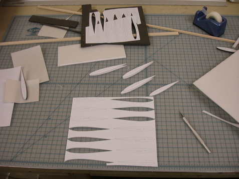
To make the wing shown above I selected an appropriate airfoil for my purpose using the UIUC airfoil database. I had a couple airfoils that I’ve used in the past and I experimented with some new ones using XFOIL to generate the lift/drag polars of the airfoils. In this particular case, I was needed a symmetrical airfoil and I used the NACA 0009.

There are various programs that will plot the airfoils for you, but I find it easiest to plot them in either excel, or your favorite plotting software. From there, you can easily scale them to have the chord length that you want.
Picture
Once you’ve scaled the airfoil, I recommend trimming it by the thickness of the skin you will be using to wrap your wing unless you’re using cloth or other extremely thin material. In my case I used 1mm depron and I subtracted 1mm from the airfoil all around the ribs so that the final wrapped wing would be the airfoil I had chosen.

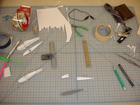
After scaling the airfoil and adjusting it for the skin thickness of your wing print out the airfoil and glue the printed piece of paper to something more rigid like card-stock or aluminum and trim. Then trim it to match your print. Now you’ve got a template for your airfoil and you just need to keep placing it on the depron sheet you’ll use to make your ribs and cut them out with an X-acto knife.

Picture
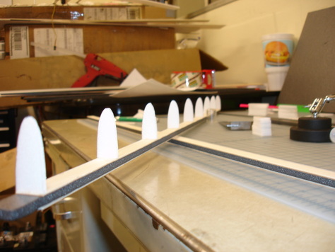
Once you’ve cut out a bunch of ribs, you’ll want to cut out a section of the rib the thickness of whatever you’ll be using for your spar about 20-30% rear of the leading edge. Now, using foam safe glue (and foam safe accelerator) glue the ribs to your spar. If you’re using a trailing edge spar, you’ll want to do a similar thing cutout toward the rear as well to leave room for your rear spar.

Picture
Glue everything together being careful not to introduce any unwanted twist to your wing. 

Picture
Once you get the wing skeleton complete it’s time to add the skin. The depron (1mm) will easily make bends with a radius of a centimeter or so, but any smaller than that can be difficult. Notice that the depron does not resist bending equally in both directions. One direction will bend fairly easily while bends made at 90 degrees to that are difficult to make. You’ll probably want to set things up such that the easy to bend direction is parallel to your wing to make construction the easiest and give your wing the most rigidity.
When making bends of a tight radius (if you’re making a small wing) I found it best to pre-crease the region in which the tightest bends were to be made by drawing lines down the depron with a dull, HB or H pencil. This crushes the depron to some degree making the bends easier. If you’re making a pretty tight bends draw many lines close together. If you’re making less tight bends you’ll need fewer lines and these can all be spaced further apart.


Get your depron all lined up with the wing and start glueing and rolling it over your ribs. You’re only minutes away from a completed extremely lightweight wing now.

The depron wing made above was used for a mockup of what was to be a VTOL UAV platform. In the two lower pictures you see the wings connected to potentiometer shafts which were in turn connected to servos via a gear mechanism.

This setup allowed me to rotate the whole wing similarly to an aileron on a normal wing. The servos were modified so that the feedback potentiometer that “tells” the servo where in its range of motion it is was disconnected and instead the leads were connected directly to the potentiometer to which the wing was attached. This setup allowed me to introduce one more gear stage to a servo thereby increasing its effective output torque while maintaining the position control that a servo has built in. You can see a video of this setup in action by clicking this link.

The skin shown on the wingtip is made of 1mm thick depron foam.

This wing actually broke during some testing at the initial stages of a project of mine. I had not adequately reinforced the inboard section of the wing and the connection between the wing and fuselage. Remember, the bending moment goes roughly with the square of the distance from the wingtip. In my case, it went with the cube (to some approximation) because my wing was spinning about the root as does a rotor on a helicopter. 
If you want to see me break my lovely wing you can check out the video below, or check out the droptest.

Rotoplane-1

9/30/2007

 
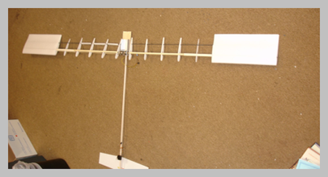
Picture
What is the Rotoplane?
    The idea behind the this project is to develop a UAV platform capable of carrying shock-sensitive electronics, such as gimbaled cameras with large telephoto lenses, while maintaining low ground support requirements. The rotoplane will combine elements from both helicopters and aircraft. It will have the ability to fly like an airplane, but also the capability of landing like a helicopter. This is admittedly a very ambitious project to undertake in the limited time available for a senior thesis. My goal is not to build the next generation UAV, but rather to prove that a vertically landing fixed-wing aircraft with a thrust to weight ratio of less than one is feasible. If I can accomplish this before my thesis is due I’ll be satisfied.

What platforms already exist?
    There already exist UAV platforms with low ground support requirements such as those developed by Aerovironment. The whole aircraft and ground station can fit in just a backpack or two. Unfortunately, the methods used for achieving the low ground support requirements come with some drawbacks. The landings are accomplished through a deep stall, and the airplane is subjected to considerable forces upon the semi-controlled impact with the ground. Although the airplane is designed for this type of landing, not all electronics are, and these landings thereby preclude carrying shock sensitive equipment.
    Another UAV manufacturer, Insitu, makes an aircraft that is capable of carrying sensitive electronic equipment such as gimbaled cameras with telephoto lenses because they have developed a landing method that reduces the accelerations during landing to levels acceptable for gimbaled camera systems. They have accomplished this through a patented Skyhook method similar to that of the tail-hook landing method of carrier-based aircraft. Unfortunately, the skyhook method requires a large amount of equipment at the landing site.

Is there a need for the Rotoplane?
    Well, it depends who you ask. The fleet of small UAVs built by Aerovironment through the Scan Eagle and up to the Global Hawk pretty well span the gamut of necessary UAVs. That said, a ScanEagle type aircraft that was capable of autonomous landings without ground support equipment would be an improvement on the ScanEagle. Over the course of my thesis I hope to develop a proof of concept of such a UAV platform.
Forward>>

    Author

    I've just got a lot of interests to put it simply. This is a portal into my thoughts, ramblings, and projects.

    Archives

    May 2016
    April 2016
    March 2016
    August 2011
    May 2011
    August 2010
    July 2010
    June 2010
    September 2009
    June 2008
    February 2008
    January 2008
    November 2007
    October 2007
    September 2007

    Categories

    All

    RSS Feed

Powered by Create your own unique website with customizable templates.